Introduction
Fuel tank inspection port installation sits in an uncomfortable middle ground: straightforward enough that many technicians attempt it without specialist help, yet demanding enough that poor execution creates real hazards. Flammable or chemically active contents leave no margin for a compromised seal or a port cut into the wrong chamber.
Trained maintenance technicians can handle smaller metallic tanks competently. Large industrial tanks and FRP (fiberglass-reinforced plastic) vessels are different — wall thickness, laminate compatibility, and SPCC regulatory compliance introduce requirements that demand certified specialists or engineer-led teams.
The consequences of skipping that expertise show up in predictable ways:
- Gasket face leaks from incorrect material selection or uneven torquing
- Ports installed in the wrong chamber of a baffled tank, leaving contamination unreachable
- Structural damage to thin-wall FRP tanks from cutting without laminate assessment
This guide walks through design decisions, installation steps, validation methods, and common failure fixes — so technicians and plant engineers know exactly what a correct installation looks like before cutting begins.
Key Takeaways
- One port per baffled chamber — a single port leaves contamination trapped in unported sections
- Minimum 120 mm diameter per ISO 21487 for diesel tanks, confirmed accessible after final installation — not just on the bench
- Drain the tank completely and verify it is vapor-free before cutting — without exception
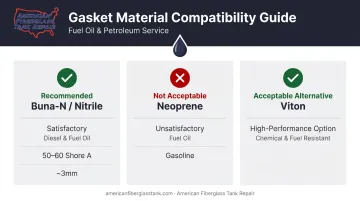
- Use Buna-N (Nitrile) gaskets for diesel fuel submersion — neoprene is not an acceptable substitute
- Pressure-test before returning to service using compressed air at the pressure marked on the tank label
Fuel Tank Inspection Port Installation Guide
Installation follows four stages: design and planning → site preparation → physical installation → validation. Most problems originate in the first and last stages — either the design wasn't thought through before the first cut, or the tank went back into service without a proper pressure test.
A single-port retrofit on a straightforward tank can take a skilled technician half a day. Multi-chamber baffled industrial tanks require more time, coordination, and often specialist involvement.
Design Considerations and Prerequisites
The one-port-per-chamber rule is the most important design principle. A tank divided by two baffles has three separate chambers. Each needs its own access port. Contamination — sludge, water, biological growth — distributes across all chambers and cannot be cleaned from an adjacent section. Technical guidance from Professional BoatBuilder and SeaBuilt's product documentation both confirm that one access point per baffled section is the correct approach for effective tank maintenance.
Minimum port diameter: ISO 21487:2022 specifies a 120 mm minimum inspection opening for diesel tanks on small craft. Older ABYC H-33 text (1989) specified 6 inches / 152 mm for tanks of 20 gallons or more; a later secondary technical reference reports 4.75 inches / 120 mm. Use 120 mm as the working benchmark, but verify against the current applicable standard for your installation context.
Ports must remain accessible after the tank is in its final installed position. A port that requires removing the tank to open it serves no practical function.
Placement — top vs. side:
- Top-surface installation is standard and most commonly compliant
- Side installation is permitted for diesel tanks under ISO 21487-related guidance and is often the only option when overhead clearance is minimal
- Side installation is prohibited for gasoline tanks — SeaBuilt's product guidance states this explicitly
- Side-mounted ports on full tanks will be submerged, which places higher demands on gasket design and sealing integrity
Material compatibility:
- Metallic tanks (aluminum, steel): port flange and cover should match the tank alloy to prevent galvanic corrosion; common aluminum alloys used for tank fitting plates include 5052, 5083, and 5086
- FRP tanks: aluminum ports are used, but the interface between dissimilar materials must be properly sealed; cutting and drilling must account for the laminate structure, which varies in thickness and layup
Gasket selection: Parker's O-Ring Handbook rates Nitrile/Buna-N as satisfactory for diesel oil and rates neoprene/chloroprene as unsatisfactory for fuel oil and gasoline. The technical benchmark from Steve D'Antonio Marine Consulting specifies Buna-N or Viton at 50–60 Shore A hardness and approximately 0.125 inches / 3 mm thickness as the preferred specification.
Do not use gasket sealing compound on mating faces. It deteriorates in fuel contact and creates worse leak paths than a properly fitted dry gasket. A light film of Teflon or silicone grease on the faces is acceptable. Gaskets must also form a complete, unbroken ring — split gaskets are not acceptable.
Tools and Materials Required
Essential tools:
- Hole saw sized to the port kit specification
- Drill and deburring tool
- Torque wrench
- Borescope or inspection light
- Respirator, gloves, and eye protection
Key materials:
- Port kit (flange, cover plate, backing ring or doubler plate, hardware)
- Buna-N gasket cut to spec (50–60 Shore A, ~0.125 in. / 3 mm)
- Inert gas supply (argon or similar) for vapor purging if required
- Fuel-proof thread sealant for threaded fittings
- Lint-free rags
On backing systems: Aftermarket split-ring backing plate systems are available for tanks where internal welding isn't possible and wall thickness is insufficient for direct thread engagement. These are not optional alternatives to structural doubler plates on thicker tanks — they serve a specific purpose for thin-wall and FRP retrofits.
With tools and materials staged, work can begin — provided the tank preparation below is complete before any cutting starts.
How to Install a Fuel Tank Inspection Port
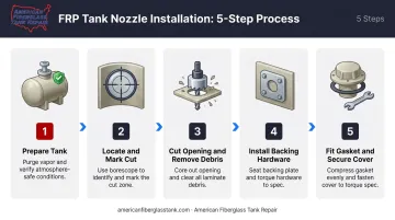
Step 1 — Prepare the tank. Confirm the tank is completely drained. Purge residual vapors using inert gas or forced ventilation. Verify the work area is ventilated and free of ignition sources. No cutting begins until the tank is confirmed vapor-free.
Step 2 — Locate and mark the cut. Insert a borescope through an existing fitting to visually confirm baffle positions before marking. Do not rely solely on drawings or schematics ; fabrication tolerances can place baffles differently than the plan shows. Mark the cut circle and double-check clearance from baffles and existing fittings.
Step 3 — Cut the opening and remove debris. Cut using the appropriate hole saw. Remove all metal or fiberglass swarf from the tank interior immediately ; debris that reaches fuel pickups can damage injection systems. For FRP tanks, the cut edge of the laminate should be sealed to prevent moisture wicking into the fiberglass structure.
Step 4 — Install the backing hardware. For retrofit installations, insert the split-ring or doubler plate through the opening and position it against the inner tank wall. Feed fasteners through pre-drilled holes. For new-construction tanks, studs should be welded from the inside during fabrication using a doubler plate ; this distributes load properly and is structurally superior to threading directly into a tank wall.
Step 5 — Fit the gasket and secure the cover plate. Place the Buna-N gasket dry (no compound) with a light grease film on the mating faces. Position the cover plate and hand-tighten fasteners in a cross pattern before torquing to the manufacturer's specification. Confirm the gasket compresses uniformly and the cover plate shows no bowing or distortion.
Post-Installation Checks and Validation
Once the tank is fully reassembled with all fittings, ports, and pickup tubes in place, pressure-test with compressed air before adding fuel. 33 CFR 183.580 requires the tank be filled with air or inert gas to the pressure marked on its label. ABYC H-33 specifies 3 psi / 21 kPa or 1.5 times maximum static head, whichever is greater; ISO 21487 uses 20 kPa or 1.5 times hydrostatic head. For industrial ASTs, the applicable tank standard and manufacturer rating govern — do not import marine psi values wholesale.
During the pressure hold:
- Apply soap solution to all port covers, gasket edges, fittings, and pipe thread connections
- Any bubbling identifies a leak that must be resolved before fuel is introduced
- This step reliably catches gasket misalignment and under-torqued fasteners
For industrial or FRP tanks, a post-installation inspection by a certified inspector catches what pressure testing cannot. A pressure test confirms the tank holds at that moment; it does not reveal laminate damage, subsurface wicking, or gasket face conditions that may cause problems weeks later.
AFTR's FTPI-certified inspectors assess laminate integrity around the cut, overall tank condition, and installation quality using ultrasonic, laser, and high-intensity backlight testing methods. This is particularly relevant for large-volume or regulated storage applications where a post-installation failure carries significant compliance and operational consequences.
Common Installation Problems and Fixes
Most installation problems fall into three predictable categories. Recognizing them early prevents rework and, more critically, undetected leaks that can compromise tank integrity.
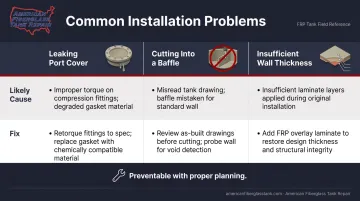
Leaking Port Cover After Installation
Problem: The port cover weeps fuel or fails a pressure test shortly after reassembly.
Likely causes:
- Gasket material not rated for prolonged fuel submersion
- Gasket compound applied to mating faces and subsequently deteriorated
- Uneven torquing causing non-uniform gasket compression
- Cover plate too thin, causing visible bowing
Fix:
- Remove the cover and inspect the gasket for swelling, cracking, or compression set
- Replace with a correctly specified Buna-N gasket
- Re-torque fasteners in a cross pattern
- If the cover plate is bowed, replace it with a heavier-gauge plate — additional torque will not correct the bow and may worsen the seal
Cutting Into or Through a Baffle
Problem: The hole saw breaks into a baffle during cutting.
Likely cause: Relying on schematics without borescope confirmation, or misidentifying baffle position from the exterior.
A baffle intrusion isn't automatically a failure. The opening can sometimes be carefully ground back to create clearance for port installation. On large or regulated tanks, any structural alteration to a baffle warrants engineer review before work continues.
Insufficient Wall Thickness for Fastener Engagement
Problem: Fasteners cannot achieve adequate thread engagement, leaving the port loose or unable to hold sealing pressure.
Likely cause: Common in thinner-wall aluminum tanks and FRP tanks where laminate thickness was not verified before specifying a direct-thread installation.
Fix: Do not over-tighten into a thin wall. Doing so damages the material and compounds the problem. Instead, retrofit a split-ring backing plate system designed for aftermarket installation. These distribute clamping load across a larger surface area regardless of wall thickness.
Pro Tips for Installing Fuel Tank Inspection Ports Effectively
Always borescope before cutting. Insert it through an existing fitting to map baffle positions and confirm interior condition. This takes minutes and prevents the most common costly errors.
Never use gasket compound on port cover mating faces. If the surfaces and gasket can't seal without compound, the real problem is a warped cover plate, wrong gasket hardness, or surface irregularities. Fix those directly: compound will eventually break down in fuel contact.
Mark and number every port cover before removal. Many covers are custom-fitted to a specific opening in a specific orientation. Swapping or reversing covers is a common cause of post-reassembly leaks that are genuinely hard to diagnose.
On regulated tanks, bring in a certified professional. FRP vessels and any tank under EPA or SPCC oversight require certified installation and post-installation inspection — not DIY work.
Under 40 CFR Part 112, inspection-port installation can constitute a material repair that triggers integrity testing requirements and potentially PE certification for SPCC plan amendments. Compliance exposure on these tanks routinely exceeds the cost of professional service.
Conclusion
Inspection port quality — both in design and installation — determines whether a tank can actually be maintained over its service life. A port in the wrong chamber, sealed with the wrong gasket material, or returned to service without pressure testing creates a failure point that compounds over time, not a maintainable asset.
Treat port installation as a planned procedure, not a reactive fix. A complete installation sequence includes:
- Vapor purging before any cutting or grinding begins
- Borescope verification of chamber placement and internal condition
- Post-installation pressure testing to confirm seal integrity
For industrial or commercial FRP tanks — chemical storage, regulated petroleum storage, water treatment infrastructure — professional inspection after installation is not optional. AFTR's FTPI-certified inspectors use ultrasonic and high-intensity backlight testing to confirm what a pressure test alone cannot, providing documented post-installation assurance for tanks where failure consequences extend beyond inconvenience.
Frequently Asked Questions
What is a fuel tank inspection?
A fuel tank inspection is a visual and structural assessment of a tank's interior and exterior, covering contamination, corrosion, laminate damage, sludge, and the condition of fittings and access ports. The goal is to confirm the tank is safe and serviceable, and to catch issues early before they require costly repair or cause failure.
What pressure (psi) is used to pressure-test a fuel tank?
The correct test pressure is marked on the tank's manufacturer label — most marine fuel tanks fall in the 3–5 psi range. Testing uses compressed air (not fuel), with all fittings reinstalled and a soap solution applied to seams, port covers, and connections to detect leaks. Industrial tanks follow the applicable standard and design rating for their tank type.
Can inspection ports be installed on the side of a fuel tank?
Side installation is permitted for diesel tanks under ISO 21487-related guidance and is often the only practical option when overhead clearance is too limited for top installation. It is prohibited on gasoline tanks. Side-mounted ports may be submerged when the tank is full, which requires careful attention to gasket integrity and sealing.
What gasket material should I use for a fuel tank inspection port?
Buna-N (Nitrile) rubber at 50–60 Shore A hardness and approximately 0.125 inches / 3 mm thickness is the verified choice for diesel fuel applications. Parker's compatibility data rates Nitrile as satisfactory for diesel and neoprene as unsatisfactory — neoprene is not an acceptable substitute. Standard rubber gaskets are not rated for prolonged fuel submersion.
How many inspection ports does a baffled fuel tank need?
One port per baffled chamber. A tank with two baffles has three chambers and requires three ports. Contamination distributes across all chambers and cannot be cleaned from a section that lacks direct access; proximity to an adjacent port does not substitute for direct access.
Can inspection ports be added to an existing fiberglass tank?
Yes. Ports can be retrofitted to most FRP tanks using aftermarket split-ring backing plate systems that accommodate thin or variable laminate thickness. Cut laminate edges must be properly sealed to prevent wicking, and on large industrial tanks, the work should be performed by technicians with FRP-specific experience given the variation in laminate structure and wall thickness.