Key Takeaways
- FRP tank design commits resin selection, laminate construction, and load capacity before fabrication — errors at this stage cannot be corrected after the fact
- Foundation engineering is non-negotiable: uneven bearing induces shell stress that FRP cannot redistribute the way steel can
- Nozzle connections are the leading failure point; flexible connectors and independent pipe supports are required at every connection
- Hydrostatic testing and professional laminate inspection before commissioning establishes the baseline condition record for all future inspections
- Scheduled inspections by certified professionals catch degradation early and can add years of service life while preventing costly unplanned failures
Key Design Guidelines for FRP Composite Tanks
Design decisions made before fabrication determine chemical resistance, structural capacity, and service life. Changes after manufacturing are expensive and technically complex. Getting it right before the purchase order is placed avoids those costs entirely.
Resin and Laminate Selection
The inner corrosion barrier (liner) is the most consequential design decision in an FRP tank project. Four resin systems cover most industrial applications:
| Resin System | General Characteristics |
|---|---|
| Isophthalic polyester | Broad chemical resistance, cost-effective for moderate service |
| Terephthalic polyester | Enhanced hydrolytic stability, suited to water and dilute chemical service |
| Vinylester | Higher chemical resistance, suitable for aggressive acids and oxidizers |
| Epoxy | Excellent resistance to alkalis, solvents, and high-temperature service |
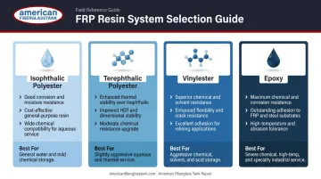
The resin must be matched to the actual stored chemical, its concentration, temperature, and fill/drain cycle frequency — not selected from a catalog default. ASTM C581 provides the standard practice for evaluating chemical resistance of thermosetting resins used in glass-fiber-reinforced structures intended for liquid service. Resin manufacturers including AOC (Vipel), Ashland (Derakane), and Reichhold (DION) publish chemical resistance guides that cross-reference resin families against specific chemicals and concentrations.
Wall thickness is governed by hydrostatic head (fluid height × density), applied live loads, wind loading based on site exposure category, and seismic zone classification. The applicable U.S. design standard for corrosion-resistant FRP equipment is ASME RTP-1 — Reinforced Thermoset Plastic Corrosion-Resistant Equipment — which covers stationary vessels for storage and processing at pressures not exceeding 15 psig.
AWWA D100 applies explicitly to welded carbon steel tanks and does not govern FRP construction. Applying steel tank engineering assumptions to FRP produces walls that are either under-designed for hydrostatic pressure or over-designed in ways that add unnecessary weight and cost.
Nozzle openings are stress concentration points. ASME RTP-1 addresses reinforcement of circular openings and cutouts. Proper nozzle design requires:
- A laminated reinforcing pad over the local shell area at every nozzle
- Independently supported piping so deadweight and thermal loads don't transfer to the tank shell
- Flexible connectors to isolate vibration at the nozzle flange
UTComp's research confirms that FRP stress corrosion cracking failures occur predominantly at nozzles and stub-ins — the locations where piping loads concentrate when flexible connectors are absent.
Tank Geometry and Accessory Planning
Geometry decisions must be made during design against process and site constraints:
- Vertical cylindrical — most common, efficient use of footprint, straightforward foundation design
- Horizontal — lower center of gravity, suited to transport or low-headroom installations, requires saddle supports engineered for FRP
- Flat bottom vs. cone bottom vs. dish bottom — affects drainability, residue management, and foundation design; cone bottoms require leg or ring support structures
Retrofitting a cone bottom or changing tank orientation after fabrication is not feasible. Accessory locations carry the same constraint — manways, vents, overflows, drain connections, level instruments, and grounding provisions must be designed into the tank drawing and confirmed against the P&ID before fabrication begins. Nozzle location conflicts discovered at installation force costly field modifications that could have been resolved on paper.
Prerequisites and Site Readiness for Integration
Three conditions must be verified before a tank arrives on site. All three become exponentially harder — and costlier — to address once the tank is in place.
Foundation Readiness
FRP tanks require full, uniform bottom support — typically a reinforced concrete pad with embedded anchor inserts, or a compacted sand bed for smaller above-ground applications. FRP shells cannot redistribute point loads the way steel can; even localized high points in a concrete pad create concentrated bending stress under hydrostatic load. Full, continuous bottom contact is a hard requirement for flat-bottom FRP installations.
Piping Coordination
Confirm that all nozzle sizes, pressure ratings, orientations, and elevations on the delivered tank match the approved design drawing and P&ID. Stub-out lengths must accommodate flexible expansion joints between the tank nozzle and the rigid piping system. Resolving those conflicts after the tank is set multiplies cost and downtime significantly.
All four of the following conditions must be satisfied before installation proceeds:
- Foundation fully cured and verified level
- Chemical compatibility of the specified resin confirmed against actual service chemical at operating concentration and temperature
- Nozzle locations reconciled against as-built piping
- Lifting and rigging plan reviewed against tank weight and shell fragility
Step-by-Step Composite Tank Integration Process
FRP tank integration follows a defined sequence. Shortcuts, particularly omitting flexible connectors or skipping foundation verification, are the leading causes of early failures that require expensive repair or full tank replacement.
Receiving and Inspection
Verify on delivery:
- Shell impacts, cracked gussets, or damaged flange faces from shipping
- Nozzle locations, sizes, and ratings against the approved fabrication drawing
- Interior corrosion barrier for voids, dry spots, or surface irregularities
- Tank marking and laminate certification documentation
Any deficiency found at this stage must be assessed and resolved before installation proceeds. Documenting a deficiency and deferring it guarantees a more expensive problem later.
Setting the Tank
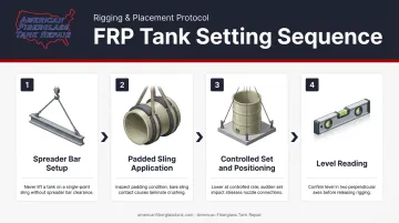
FRP-specific rigging requirements:
- Use a spreader bar to distribute lift loads and prevent shell crushing
- Never wrap chains or wire rope directly on laminate surfaces; use padded slings only
- Set slowly and guide the tank into final position without dragging across the foundation
- Take an initial level reading immediately after setting, before any connections are made
Anchor and Restraint Installation
FRP tanks use non-compressive hold-down methods — laminated lugs or bonded anchors that secure the tank without penetrating or compressing the shell wall. ASME RTP-1 includes guidance on hold-down lug design and seismic and wind loading considerations, and Composites USA fitting standards require wind exposure and seismic zone data as inputs to lug design.
Anchor design must also accommodate thermal expansion. Rigid anchoring that prevents all tank movement induces shell stress under temperature cycling, a failure mode that develops gradually and becomes difficult to diagnose once the tank is in service.
Nozzle-to-Piping Connection
This is the step most commonly executed incorrectly:
- Install flexible expansion joints or flexible couplings at every nozzle-to-piping interface — no exceptions
- Confirm flange faces are parallel and aligned before bolting; do not use bolt torque to pull misaligned flanges together
- Verify gasket material compatibility with the stored fluid before installation
- Complete all nozzle connections before backfilling or grouting around the tank base
Pulling misaligned flanges into position with bolts imposes a permanent bending load on the nozzle reinforcement pad. That load is present from day one and compounds with every thermal cycle.
Accessories and Final Integration
With structural connections complete, close out the installation with these final steps:
- Install vents, overflow lines, level instruments, manway hardware, and grounding or bonding provisions
- Verify all gasketed joints use chemically compatible gasket material
- Conduct a P&ID walk-down to confirm no connections were missed
- Document the as-built configuration — nozzle locations, flange ratings, gasket materials — in the tank record file
Post-Integration Checks and Validation
Hydrostatic Testing
Fill the tank with clean water to the maximum operating level and hold for a minimum of 24 hours while observing all nozzle connections, seams, shell surfaces, and the bottom for weeping or distortion. Spunstrand's FRP chemical tank specifications describe this approach: fill to the top nozzle, allow it to stand overnight, and check for visible leakage.
Water is the correct test medium for FRP storage tanks at atmospheric pressure. Pneumatic pressure testing with air or gas stores far more energy in a compressed state — a failure under pneumatic test conditions releases that energy suddenly, with none of the controlled dissipation water testing provides.
Any seepage at nozzle connections or shell seams, visible distortion, or flat-spotting of the shell during the hold period constitutes a failure requiring investigation before the tank enters chemical service.
Professional Laminate Inspection
Hydrostatic testing confirms whether the tank holds fluid. Laminate inspection confirms whether the shell is structurally sound.
AFTR's inspection services , supervised by Fiberglass Tank & Pipe Institute certified inspectors, use three complementary methods:
- Ultrasonic thickness measurement — measures wall thickness from one side, detects internal voids and capillary migration beneath the corrosion coat
- High-intensity backlight inspection — reveals delamination, liquid penetration patterns, and structural body defects not visible at the surface
- Laser scanning — provides dimensional analysis and detects shell distortion
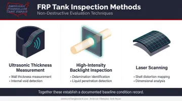
Together these methods establish a documented baseline condition record. That baseline is essential for future maintenance decisions: without it, there is no objective way to determine whether degradation found at a later inspection was present at commissioning or developed in service.
Why Skipping Validation Is a Serious Risk
Small seepage at nozzles or hairline surface crazing that appears cosmetic at commissioning indicates laminate stress cracking. Under cyclic fill, drain, and thermal loading, those cracks propagate. Catching them before the tank enters chemical service keeps a minor laminate repair from becoming something far costlier:
- A product spill requiring containment and cleanup
- A regulatory incident triggering agency notification
- An emergency shutdown that halts production
Common Composite Tank Integration Problems and Fixes
Nozzle Stress Cracking
Problem: Cracking or seepage at the nozzle-to-shell junction, typically within the first months of service.
Likely cause: Piping deadweight, thermal expansion, or vibration transferring into the tank shell because flexible expansion joints were omitted or piping lacks independent support between the nozzle and the next rigid anchor point.
Fix:
- Drain and depressurize the tank
- Install flexible expansion joints at each affected nozzle connection
- Add independent pipe supports to remove load from the nozzle
- Assess laminate cracking extent before returning to service — surface crazing may be repairable in place, but cracking that extends through the reinforcement layer requires professional evaluation
Shell Distortion or Bottom Cracking
Problem: Shell flat-spotting, waviness, or circumferential cracking discovered during or shortly after initial fill.
Likely cause: Non-uniform foundation bearing — high spots on the concrete pad create concentrated point loads that FRP cannot redistribute, inducing localized bending stress. Common when tanks are set on aged pads originally designed for steel tanks.
Fix:
- Drain the tank
- Survey the foundation to identify bearing non-uniformity
- Re-grout or re-level the pad to achieve uniform contact; for sand-bed installations, re-compact and re-level
- Assess laminate condition in affected areas before refilling
Internal Liner Degradation
Problem: Blistering, delamination, soft spots, or discoloration of the inner corrosion barrier at first internal inspection, often within one to three years of commissioning.
Likely cause: Two distinct causes are common:
- Resin incompatibility — wrong resin specified, or service conditions changed from the original design basis
- Under-cure during fabrication — produces a corrosion barrier with higher permeability than designed
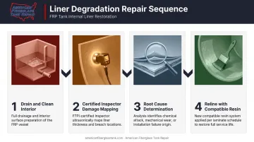
Fix:
- Drain and clean the tank interior
- Engage a certified inspector to map damage extent using ultrasonic and backlight methods
- Determine root cause before repairing — relining over an incompatible resin without changing the system will repeat the failure
- Reline with a compatible resin system matched to the actual service chemical, concentration, and temperature
When root cause points to resin incompatibility, material selection becomes the critical repair decision. AFTR's repair and relining services use custom-blended isophthalic, terephthalic, vinylester, and epoxy formulations selected against the specific chemical environment, concentration, and temperature — not a one-size-fits-all layup.
Frequently Asked Questions
What are composite tanks?
Composite tanks are vessels constructed from fiber-reinforced polymer (FRP) materials, meaning fiberglass reinforcement embedded in a thermosetting resin matrix. They offer corrosion resistance, light weight, and long service life compared to steel, making them standard in chemical processing, water treatment, and wastewater applications.
What are the three types of water tanks?
The three common classifications are elevated tanks (raised on a support structure to provide gravity pressure head), ground-level storage tanks (at or near grade, requiring pumps for system pressure), and below-ground or underground tanks. FRP construction is used across all three types.
What design standard applies to FRP composite storage tanks?
ASME RTP-1 — Reinforced Thermoset Plastic Corrosion-Resistant Equipment — is the primary U.S. standard governing FRP tank design, covering vessels for storage and processing at pressures not exceeding 15 psig. ASTM D3299 covers filament-wound FRP tank fabrication, while D4097 applies to contact-molded construction.
How long do composite fiberglass tanks last?
With the right resin system, proper installation, and a scheduled maintenance program, FRP tanks routinely deliver 30+ years of service. The single biggest variable is liner condition — catching degradation early through periodic inspection is what separates a 20-year tank from a 40-year one.
How do I know if my composite tank needs repair or inspection?
Watch for any of these warning signs:
- Surface crazing or blistering on the shell
- Seepage at nozzles, flanges, or seams
- Soft spots or delamination on the inner liner
- Unexplained product contamination
- Tank past its scheduled inspection interval
AFTR's certified inspectors use ultrasonic, laser, and high-intensity backlight testing to detect subsurface degradation that visual checks miss.
Can a composite FRP tank be modified after installation?
Yes. Adding nozzles, extending height, and relining are all feasible after installation. Modifications must be engineered and executed by qualified FRP professionals using compatible laminate materials and proper secondary bonding procedures — unauthorized field work risks structural compromise and may void existing tank certification.