Key Takeaways
- FRP tank performance depends on liner chemistry, resin selection, fiber architecture, and nozzle design — not just material type
- The corrosion barrier (inner liner) is the most chemically critical layer and the first place degradation appears
- Resin selection (polyester vs. vinyl ester vs. epoxy) must match the specific stored chemical — no single resin works for all applications
- ASME RTP-1 governs most industrial FRP tanks up to 15 psig; ASTM D3299/D4097 cover construction methods
- Tanks with proper design and regular inspection can remain in service for 30–40 years or more
The Anatomy of an FRP Tank: Understanding Its Layered Construction
Two FRP tanks can look identical from the outside and perform completely differently. The difference lives in their laminate construction : a precisely engineered stack of functional layers, each serving a distinct role.
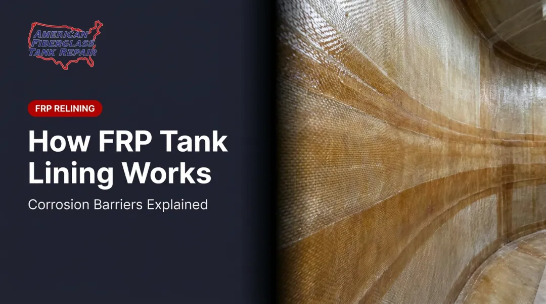
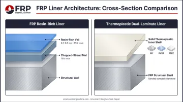
Corrosion Barrier (Inner Liner)
The inner liner is the most chemically critical layer. It contacts the stored fluid directly and must resist chemical attack without contributing structural strength.
Key characteristics:
- Thickness: Typically 2.5–6.3 mm (100–250 mils), with an initial resin-rich veil layer of 0.3–0.8 mm (10–20 mils) at approximately 95% resin content, backed by chopped-strand mat at roughly 75% resin
- Reinforcement: C-glass or synthetic veil (such as Nexus or Harlar) rather than structural E-glass — chosen for acid resistance, not strength
- Purpose: Chemical protection only; structural contribution is minimal by design
There are two distinct liner architectures. An FRP resin-rich liner uses resin-saturated glass veil and mat. A thermoplastic liner (dual-laminate construction) uses a solid thermoplastic inner shell — PP, PVC, PVDF, ECTFE, ETFE, FEP, or PTFE — bonded inside an FRP structural shell. These are fundamentally different systems requiring different repair approaches.
The liner is also where degradation starts. AFTR's field inspections routinely identify spidering, disbondment, emulsification, abrasion wear, and capillary migration of product beneath the corrosion coat — all originating in this layer. Sodium hypochlorite is among the most aggressive chemicals for FRP liners, requiring careful resin, veil, and cure selection.
Structural Wall Layer
The structural wall provides mechanical strength against hydrostatic pressure, wind, seismic loads, and vacuum. It uses E-glass fiber reinforcement built up in multiple plies, with fiber content ranging from roughly 35% by weight in hand lay-up to 70% or more in filament-wound construction.
Fiber orientation is engineered deliberately for the load demands of each application:
- Hoop winding (fibers near 90° to the tank axis) maximizes circumferential strength for internal pressure resistance
- Helical winding adds axial and combined-load capacity for tanks subject to wind, seismic, or vacuum conditions
- Hand lay-up plies supplement winding where geometry or access limits machine-applied reinforcement
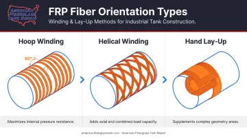
This anisotropic design gives FRP a higher tensile strength-to-weight ratio than steel in the hoop direction — a key reason filament-wound tanks are specified for high-pressure chemical service.
Outer Layer and UV Protection
The outer layer protects the structural laminate from UV degradation : surface embrittlement, porosity, and reduced impact resistance that accumulate over years of outdoor exposure. Protective measures include exterior gelcoats, pigmented resins, and UV-stabilizing additives. For outdoor installations, aliphatic UV-resistant coatings are commonly specified.
UV degradation is one of the failure modes AFTR's exterior inspection protocols specifically target. Left unaddressed, surface embrittlement progresses into laminate porosity — at which point restoration requires significantly more material and labor than early-stage intervention would have.
Key Structural Design Features of FRP Tanks
Wall Thickness and Fiber Orientation
Wall thickness is calculated — not estimated. The calculation accounts for:
- Tank diameter and liquid height (hydrostatic head)
- Internal and external pressure
- Wind and seismic loading
- Safety factors per applicable design standards
Filament winding gives fabricators precise control over fiber angle. The result is a wall optimized for the specific load profile of that tank, which is why wall thickness alone tells you very little without knowing the fiber architecture behind it. That structural engineering extends to every feature of the tank — including its openings.
Nozzles, Flanges, and Fittings
Every opening in an FRP tank — inlet, outlet, vent, drain, manway — is a structural interruption. Properly engineered nozzles require additional laminate reinforcement around the penetration to restore the load-carrying capacity removed by the opening.
Field data confirms that nozzle and penetration areas are documented leak initiation points. Improperly fabricated original nozzles and unauthorized field modifications both increase failure risk.
AFTR's nozzle repair work addresses these failure points through a structured process:
- Removes old FRP nozzles and prepares the surrounding laminate
- Seals the internal laminate to prevent product migration
- Installs shop-fabricated replacement nozzles laminated integrally into the shell, with resin and veil systems selected for the stored chemical and operating temperature
Dual Wall (Secondary Containment) Design
Dual-wall FRP tanks consist of an inner tank surrounded by an outer structural shell, with a monitored interstitial space between them. This design is used where chemical spills carry regulatory or environmental consequences — chemical storage, fuel storage, and similar applications.
The interstitial space is typically connected to leak detection systems. EPA describes this interstitial monitoring method as secondary containment with continuous leak detection capability, a recognized release detection method for underground storage tanks.
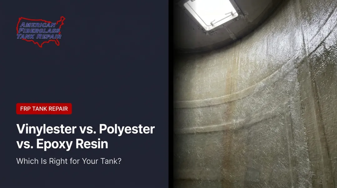
Resin and Fiber Selection: Matching Materials to Chemical Demands
Resin selection is the most consequential design decision in an FRP tank. The resin matrix determines chemical resistance, temperature limits, and long-term compatibility with the stored fluid. There is no universal default.
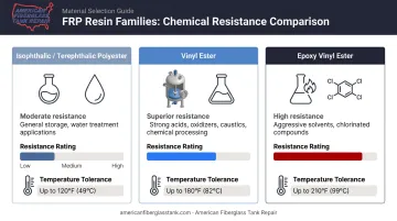
Resin Types and Their Trade-offs
| Resin Family | Chemical Resistance Profile | Typical Applications |
|---|---|---|
| Isophthalic/Terephthalic Polyester | Moderate — suitable for many acids, water, mild chemicals | General storage, water treatment |
| Vinyl Ester | Superior — strong acids, oxidizers, caustics, elevated temperatures | Chemical processing, wastewater |
| Epoxy Vinyl Ester | High — aggressive solvents, chlorinated compounds | Demanding chemical environments |
Critical caveat: Temperature limits are chemistry-specific, not universal. A vinyl ester resin like Derakane 441-400 carries an HDT of 120°C (248°F), but the actual service limit depends on the specific chemical, concentration, and pH, not the HDT alone. Resin selection must reference manufacturer chemical resistance charts, not generic temperature ceilings.
AFTR selects from custom-blended isophthalic, terephthalic polyester, vinyl ester, and epoxy resins based on the stored chemical and operating temperature. For aggressive chemicals like sodium hypochlorite, ferric chloride, and HCl, resin selection, cure method, and veil system are all critical variables.
Fiber Reinforcement and Chemical Compatibility Verification
Fiber selection follows the same chemical-specific logic. AFTR's inventory includes over 45 mat, chopped strand, and veil laminates, with each chosen based on the chemical environment:
- E-glass (electrical grade) — standard reinforcement for structural walls
- C-glass — used in corrosion liners where acid resistance is the priority
- Synthetic veils (Nexus, Harlar, carbon veil) — applied in the liner for superior chemical barrier performance
Before any relining or repair work, chemical compatibility must be verified against manufacturer resistance charts. The Derakane chemical resistance guide is one widely used reference — specifying resin selection by chemical name, concentration, pH, and operating temperature. Storing an incompatible chemical in a misspecified tank, even briefly, can cause rapid liner degradation.
Tank Configuration Options
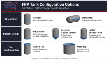
FRP tanks are configurable to match space, process, and drainage requirements.
Orientation:
- Vertical — most common for large stationary storage; maximizes capacity per footprint
- Horizontal — preferred for transport (tanker trailers), gravity-fed systems, and tight vertical clearances
Bottom design:
- Flat — simpler installation, standard for most applications
- Conical or sloped — facilitates complete drainage of corrosive or viscous fluids
- ASME dished/elliptical heads — required for pressure-rated applications
Top configuration:
- Closed top with integral roof — used for volatile, hazardous, or regulated contents
- Open top — suitable where access is frequent and contents are non-hazardous
Cylindrical tanks are most common. Rectangular and square configurations exist for space-constrained installations but require more complex structural engineering to manage flat wall loading.
Size range: Shop-fabricated FRP tanks can reach up to 21 ft 6 in (approximately 6.5 m) in diameter, with larger diameters achievable via barge shipment. Field-fabricated tanks can exceed 50 ft in diameter. The right approach depends on shipping route, site access, and application requirements — not a fixed size cutoff.
Accessories — ladders, level gauges, sight glasses, manways, vents — should be specified at the design stage alongside nozzle placements. Retrofitting them later requires the same reinforcement work as adding a new penetration, making upfront planning the more cost-effective path.
FRP Tank Design Standards You Should Know
FRP tanks used in industrial and municipal applications must be designed per recognized standards for safety, regulatory compliance, and insurability.
| Standard | Scope | Key Limits |
|---|---|---|
| ASME RTP-1 (2025) | Stationary reinforced thermoset plastic vessels | Up to 15 psig internal pressure |
| ASME Section X | FRP pressure vessels | 15 psig and above |
| ASTM D3299-24 | Filament-wound FRP tanks, aboveground vertical | Atmospheric pressure |
| ASTM D4097-19 | Contact-molded FRP tanks | Materials, design, construction |
| EN 13121-3:2016 | GRP tanks above ground (European) | Up to 10 bar, -40°C to 120°C |
| AWWA D120-19 | FRP tanks for waterworks use | Atmospheric, potable requires NSF/ANSI 61 |
| NSF/ANSI 61 | Drinking water contact components | Potable water applications |
ASME RTP-1 is the dominant North American standard for corrosion-resistant FRP vessels. It governs hoop and axial stress calculations, material property documentation, and inspection requirements — with Young's modulus values required for anisotropic laminates. Tanks exceeding 15 psig fall under ASME Section X instead.
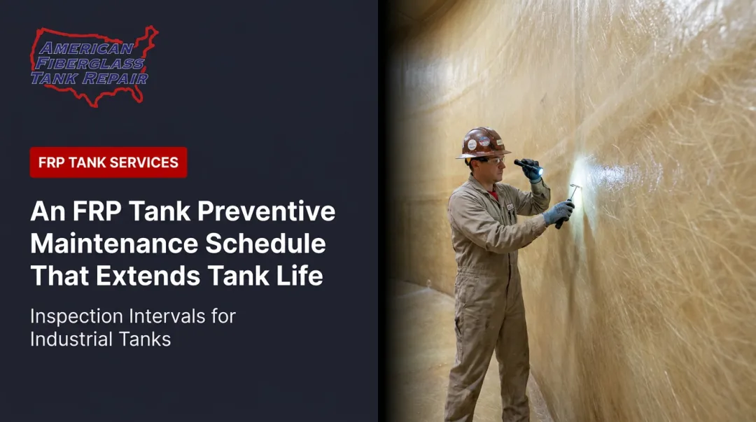
FTPI RP 2007-1 provides in-service inspection guidance, calling for trained external inspections every 5 years for hazardous-substance service, or every 10 years for tanks over 10,000 gallons in other services. AFTR's inspection services follow this protocol directly, with all inspections supervised by Fiberglass Tank & Pipe Institute certified inspectors.
How FRP Tank Design Affects Long-Term Service Life
A well-designed FRP tank can remain in service for 30–40 years in many chemical environments, according to resin supplier performance data. That lifespan depends on three things: quality fabrication, compatible resin selection, and regular inspection.
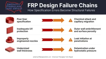
The connection between design decisions and degradation risk is direct:
- Poor liner specification → chemical attack and capillary migration beneath the corrosion coat
- Inadequate UV protection → outer wall embrittlement and surface porosity
- Improperly engineered nozzles → leak initiation at penetrations
- Undersized wall thickness → delamination under sustained hydrostatic pressure
Each of these failure modes can progress silently for months before becoming visible. AFTR's testing methods — ultrasonic, laser, and high-intensity backlight — are specifically designed to detect them before they become catastrophic. A hydrostatic test tells you whether a tank holds liquid right now. It won't tell you about capillary migration working through the laminate, or a liner that will fail in three months. AFTR's inspection approach identifies those conditions while repair is still straightforward.
For tanks without original design documentation — inherited vessels or undocumented units — AFTR's FTPI-certified inspectors use Barcol hardness testing, ultrasonic measurement, and laminate assessment to characterize the existing construction.
From that assessment, composite engineers select compatible repair resins and veil systems from an inventory of custom-blended resins and over 45 laminate materials, matching the repair to both the existing tank construction and the chemical service it needs to survive.
The practical outcome: what could have been a tank replacement becomes a planned relining project, extending service life by years without removing the vessel from its foundation.
Frequently Asked Questions
How do FRP tank designs differ from PP tanks?
FRP tanks use a glass fiber-reinforced resin composite that delivers high structural strength, design flexibility, and broad chemical resistance — including support for large-diameter and pressure-rated vessels. Polypropylene tanks handle certain acids and alkalis well but top out around 212°F and lack the structural capacity for large or pressure-rated applications.
What are the standard sizes for FRP tanks?
FRP tank sizes are not strictly standardized — they are custom-engineered. Shop-fabricated tanks typically reach up to 21 ft 6 in in diameter; larger diameters are possible via barge shipment or field fabrication. Common industrial FRP tanks range from a few hundred gallons to hundreds of thousands of gallons.
What is the design pressure for FRP tanks?
ASME RTP-1 governs FRP tanks operating at up to 15 psig internal pressure aboveground. Design pressure is calculated based on wall thickness, fiber orientation, safety factors, and operating temperature. Tanks exceeding 15 psig fall under ASME Section X for FRP pressure vessels.
What is the maximum burial depth for FRP tanks?
Burial depth depends on the specific tank design, soil conditions, and traffic loading. Xerxes standard underground fiberglass tanks, for example, specify a maximum of 7 ft of cover without written manufacturer authorization. Always follow the tank manufacturer's installation manual — exceeding specified depths without engineering review can lead to structural failure.
What resins are used in FRP tank design?
The most common resins are isophthalic/terephthalic polyester (general-purpose), vinyl ester (aggressive chemical resistance), and epoxy vinyl ester (highest-demand environments). Selection depends on the chemical stored, its concentration, operating temperature, and applicable standards.
How long do FRP tanks last?
With proper design and regular inspection, FRP tanks can remain in service for 30–40 years or more. Longevity depends on corrosion liner quality, UV protection, resin-chemical compatibility, and consistent periodic inspections that catch early-stage degradation before it escalates.