Introduction
Clarifier tanks are found in virtually every municipal and industrial wastewater treatment plant on the planet. They handle one of the most fundamental tasks in the treatment sequence: separating suspended solids from liquid before downstream processes begin.
Yet despite being so common, how clarifiers actually work is frequently misunderstood. Many operators and facility managers know they "settle out solids" — but lack a working understanding of the internal zones, hydraulic variables, and mechanical components that determine whether a clarifier performs as designed or becomes a compliance liability.
That gap leads to real problems:
- Overlooked sludge blanket buildup that disrupts effluent quality
- Undetected weir damage causing uneven flow distribution
- Tank lining degradation that erodes structural integrity until a failure forces the issue
This guide explains how clarifier tanks work in practice — covering the operating principle, internal zones, types, and the operational variables that separate a well-run clarifier from a struggling one.
Key Takeaways
- A clarifier uses gravity to separate suspended solids from wastewater, producing clarified effluent and concentrated sludge
- Water moves through four zones — inlet, settling, sludge collection, and effluent discharge — each governed by distinct hydraulic requirements
- Primary clarifiers handle raw solids before biological treatment; secondary clarifiers separate biomass after it
- Performance is controlled by surface overflow rate, hydraulic retention time, sludge blanket depth, and weir condition — not tank size alone
- FRP lining condition inside clarifier tanks directly affects treatment performance and requires periodic professional inspection
What Is a Clarifier Tank?
A clarifier tank is a mechanized sedimentation vessel engineered to continuously remove suspended solids from liquid through gravity settling. It produces two outputs: clarified effluent (water with reduced solids) and sludge (concentrated settled material).
Unlike a basic settling pond — which relies on gravity alone — a clarifier adds rotating scrapers, surface skimmers, and overflow weirs. Those components enable continuous, controlled operation at treatment-plant scale.
The Water Environment Federation describes sedimentation as one of the most widely used processes in wastewater treatment — and often the last gravity barrier before effluent leaves the plant.
Clarifiers also hold a meaningful energy advantage over newer alternatives like Membrane Bioreactors (MBRs). EPA notes that MBRs require continuous air scouring to control membrane fouling, an energy overhead that conventional clarifiers avoid entirely.
Primary vs. Secondary Clarifiers
The two main types serve different stages of treatment:
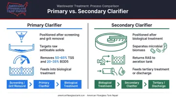
- Primary clarifiers — positioned after screening and grit removal, they target raw settleable solids and organic matter. According to EPA's 2023 operator training, primary clarifiers typically remove 50–65% of TSS and 20–35% of BOD5, reducing the load entering biological treatment
- Secondary clarifiers — positioned after biological treatment (typically activated sludge), they separate microbial biomass from treated water and return settled biomass to the aeration tank
Design variants include horizontal flow (rectangular), vertical flow (circular), and inclined plate/lamella clarifiers, which use angled plates to multiply effective settling surface area within a smaller footprint. The core operating principle — gravity sedimentation — is identical across all three.
How Does a Clarifier Tank Work?
Clarifier tanks operate through a defined sequence of internal zones. The process is continuous and gravity-driven, with mechanical components assisting at key stages.
Zone 1: Influent Entry and Flow Distribution
Wastewater enters through a central inlet (circular clarifiers) or end inlet (rectangular clarifiers) fitted with energy-dissipating baffles or diffusers. Both reduce turbulence and spread flow evenly across the tank's cross-section.
When this fails, short-circuiting occurs: water moves through faster than the design flow path, reducing effective settling time and carrying solids into the effluent. Common causes include:
- Unlevel weirs and temperature gradients (per Kentucky's wastewater operator manual)
- Density differences between mixed liquor and clarified liquid (per EPA clarifier modeling work)
In some systems, operators add chemical coagulants or polymers upstream to bind fine particles into larger, denser flocs that settle faster. This is standard in high-rate clarifiers and industrial applications where particle characteristics make unaided settling insufficient.
Zone 2: Gravity Settling
This is the largest zone and the functional core of the clarifier. As water slows and spreads, gravity pulls heavier suspended solids downward while clarified water rises toward the surface.
Two design parameters govern this zone:
- Hydraulic Retention Time (HRT) — the time water spends in the tank. EPA benchmarks: primary clarifiers need 1.5 to 3.0 hours; secondary clarifiers need 3 to 4 hours
- Surface Overflow Rate (SOR) — volume of flow per unit of tank surface area per unit time. WEF gives typical primary SOR of 800–1,200 gpd/sf at average flow and secondary SOR of 400–700 gpd/sf
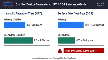
Exceeding design SOR is one of the most common causes of clarifier upsets. The Ten States Standards note that significant reduction in primary BOD removal can occur when peak hourly overflow exceeds 1,500 gpd/ft².
Zone 3: Sludge Collection and Scum Removal
Settled solids accumulate at the tank bottom as a sludge blanket. Removal mechanisms differ by tank geometry:
- Circular clarifiers — rotating scraper arms (typically moving at 10–15 ft/min per EPA benchmarks) sweep sludge toward a central hopper
- Rectangular clarifiers — chain-and-flight collectors drag sludge along the floor to collection hoppers
Sludge left too long becomes anaerobic, generates gas, and causes floating solids — creating a direct compliance risk that operators can see at the surface.
Surface skimmer arms address a parallel issue: oils, grease, and foam continuously swept into a scum box for separate disposal. Without functional skimmers, floating material degrades effluent quality and creates odor problems downstream.
Zone 4: Clarified Effluent Discharge
Clarified water rises to the surface and exits over overflow weirs — typically peripheral weirs running around the top edge of circular clarifiers. Weir design distributes outflow evenly to prevent localized high-velocity zones that would pull settled solids upward.
Weir loading rate (flow per unit weir length) is a key parameter. The Ten States Standards set peak-hour limits of 20,000 gpd/linear ft for plants under 1 MGD and 30,000 gpd/linear ft for larger facilities.
After primary clarification, effluent moves to biological treatment. After secondary clarification, it proceeds to tertiary treatment or discharge.
Secondary clarifiers carry one additional responsibility: returning a portion of settled biomass as Return Activated Sludge (RAS) to the aeration tank. This maintains the microbial population driving biological treatment. Typical RAS flow targets range from 50–150% of influent flow depending on process conditions.
Key Operational Factors That Affect Clarifier Performance
Understanding the zones is the foundation — but day-to-day performance depends on how well these four operational variables are managed.
Sludge Blanket Depth
The sludge layer at the tank bottom must be monitored and actively managed. If the blanket rises too high, it compresses the settling zone and allows solids to escape over the weirs.
WEF guidance recommends keeping blanket depth in the 1 to 3 ft range, ideally 2 ft or less. Monitoring tools include the Sludge Judge (a manual sampling tube), ultrasonic analyzers, and optical sensors. Blanket trending — not just spot checks — is what catches rising conditions before they become effluent TSS events.
Peak Flow Management
Storm events and industrial surges push SOR above design limits. When that happens, settling efficiency drops and solids carry over into the effluent. Well-operated plants manage this through equalization basins, flow splitting across multiple clarifier units, or operational adjustments to sludge withdrawal.
The Ten States Standards require multiple settling units for plants above 100,000 gpd design average flow — partly for redundancy, partly to maintain design SOR during peak conditions.
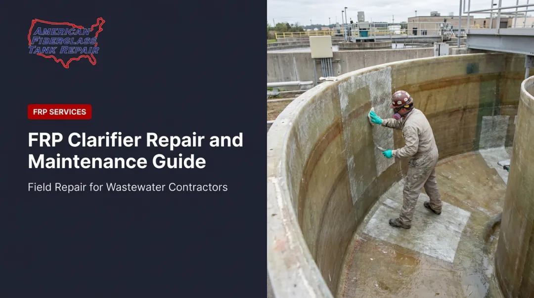
Tank Lining and Structural Condition
For FRP clarifier tanks, the internal corrosion lining is a performance variable, not just a maintenance item. The FTPI's FRP standards document that chemical exposure — through hydrolysis, oxidation, or incompatible chemical contact — can degrade laminate properties significantly, with some test conditions showing reductions to 50% of original flexural strength and 30% of original impact resistance.
A degraded lining allows permeation into the laminate structure, accelerating both structural weakening and contamination risk. Surface inspection alone misses many of these conditions.
AFTR's field inspection teams use multiple testing methods to detect subsurface degradation:
- Ultrasonic testing — identifies laminate thickness loss and internal delamination
- High-intensity backlight testing — reveals voids and corrosion coat breakdown
- Laser testing — detects capillary liquid migration and subsurface disbondment
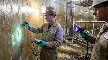
These inspections are supervised by Fiberglass Tank & Pipe Institute certified inspectors and produce detailed condition reports with repair recommendations — giving plant operators a documented basis for decisions rather than guesswork.
Weir Levelness and Condition
Uneven weirs create uneven outflow — higher velocity on one side pulls settled solids upward, increasing effluent TSS on that side of the tank. EPA's primary clarifier training specifically links unlevel weirs to short-circuiting and poor flow distribution. The Ten States Standards require overflow weirs to be readily adjustable throughout the structure's life to correct for differential tank settlement.
Scheduling weir inspection and adjustment on a regular basis — rather than waiting for the annual shutdown — prevents the short-circuiting that drives effluent TSS violations.
Where Clarifier Tanks Are Used
Clarifiers are standard equipment across a wide range of treatment environments:
- Municipal sewage treatment — both primary and secondary stages
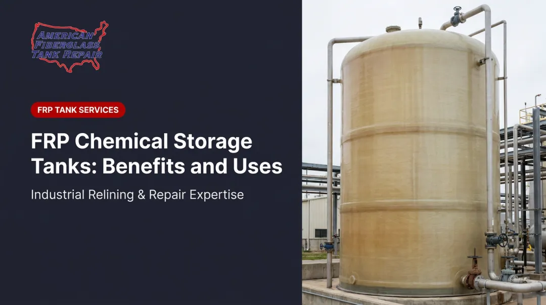
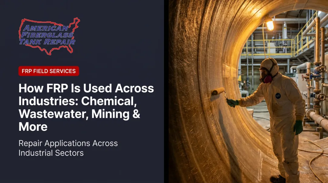
- Industrial wastewater treatment — chemical manufacturing, food and beverage processing, pharmaceutical and textile production
- Potable water treatment — conventional sedimentation basins and plate/tube settler configurations
- Pulp and paper processing — where FRP construction is common due to the chemical aggressiveness of process streams
In each of these settings, clarifier performance ties directly to permit compliance. Federal secondary treatment standards under 40 CFR Part 133 set effluent limits of 30 mg/L BOD5 and TSS on a 30-day average, 45 mg/L on a 7-day average, and 85% average removal for both parameters. A secondary clarifier that underperforms doesn't just affect effluent quality — it puts the facility's discharge permit at risk.
Conclusion
The clarifier tank's operating principle comes down to one thing: slow the water down and let gravity do the work. The engineering lives in the details — the sequence of zones, the mechanical components at each stage, and the hydraulic parameters that must stay within design limits for the process to function as intended.
Operators who understand settling zones, sludge blanket dynamics, and tank condition are better positioned to catch performance issues before they become compliance events. A rising sludge blanket, an unlevel weir, or a degraded FRP lining each traces back to a specific mechanism — and each has a specific corrective action. Knowing those mechanisms — and acting on early warning signs — keeps treatment performance consistent and avoids the unplanned downtime that compliance violations bring.
Frequently Asked Questions
What is a clarifier in water treatment?
A clarifier is a mechanized sedimentation tank that removes suspended solids by allowing gravity to settle heavier particles while clarified water rises and exits over overflow weirs. Rotating scrapers, skimmers, and weirs enable continuous solids removal across both primary and secondary treatment stages.
How do you maintain a clarifier tank?
Core tasks include withdrawing sludge regularly to prevent blanket buildup, inspecting weirs for levelness, and verifying scraper and skimmer operation. FRP internal linings also require periodic inspection for corrosion, disbondment, or structural degradation that hydrostatic testing alone won't detect.
What is the difference between a primary and secondary clarifier?
Primary clarifiers remove raw suspended solids and reduce organic load before biological treatment, typically achieving 50–65% TSS removal. Secondary clarifiers separate biological floc from water after the treatment stage and also facilitate the return of settled biomass (RAS) to the aeration tank to sustain the biological process.
What is the difference between a clarifier and a sedimentation tank?
The terms are largely interchangeable — WEF explicitly notes that primary sedimentation tanks are also called primary clarifiers. In practice, a clarifier includes mechanical components (scrapers, skimmers, weirs) for continuous solids removal, while a basic sedimentation tank may rely on gravity alone.
What causes a clarifier to fail or underperform?
Common causes include hydraulic overloading, excessive sludge blanket depth, short-circuiting from unlevel weirs, and degraded internal linings that allow permeation. Most clarifier upsets trace back to hydraulic or solids-inventory control failures rather than equipment malfunction.
How long does a clarifier tank last?
Lifespan depends on construction material, influent chemistry, and maintenance discipline. FRP tanks can achieve long service lives, but passing a hydrostatic test doesn't rule out subsurface lining degradation. Periodic inspection by qualified FRP inspectors is the only reliable way to assess actual remaining service life.